C
E
Picor Corporation ?picorpower.com
QPI-8
Rev 1.5, Page 9 of 17
QPI-8
QUIETPOWER
?/DIV>
QPI-8 Timing Waveforms
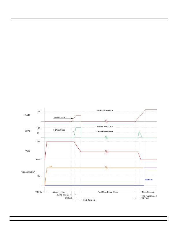
The waveforms in Figure 17 are the typical start-up
waveforms that would be seen in a system where two current
pulses are required to completely charge the bulk
capacitance to the bus voltage. The GATE waveform is an
internal signal and cannot be measured externally; it is shown
only for reference.
Once VIN is established and the UV and OV thresholds are
satisfied, the internal FETs gate will start to get driven high
after a 15ms delay. This delay allows for insertion de-
bouncing. As the FET turns
on
and allows the passing of
current the magnitude of the current is monitored. Once it
reaches the 6A circuit breaker threshold an internal fault
timer is started and the current is limited to a 12A maximum
value. If the current does not drop to a value below the 6A
circuit breaker limit before the fault timer ends then the gate
is shut
off
and remains off for about 95ms. After this time
the gate is again turned on and current is allowed to pass.
Once the current is below the circuit breaker limit, the FET is
fully turned
on
to its minimum r
ds
value and the Powergood
pin is released (open drain).
The change in voltage across VSW is dependent upon the
value of the bulk capacitance that the QPI-8 is charging. The
circuit breaker fault time is 300us when the voltage on VSW is
greater than 40V, referenced to BUS-; or if there is no voltage
change across VSW during the 12A current pulse, indicating a
short across the bulk capacitor. Once below the 40V limit,
and a decreasing voltage across VSW, the fault time is
increased to 1.2ms to charge the bulk capacitors faster.
The timing waveforms for an OV (Over-voltage) and UV
(Under-voltage) events are shown in Figure 18. After the
initial start-up delay, the internal FETs gate is turned on.
Once its gate-to-source voltage reaches 8V it releases the
PWRGD pin and allows it to get pulled up to VIN.
In the event of an OV fault, the QPI-8 will turn off its internal
FET and it will remain off until the OV fault is cleared. Once
cleared, the gate immediately starts to turn back on. With an
UV fault, the FET is again turned off, but the gate is not
turned back on until 15ms after the UV fault has been
cleared.
Figure 17 - QPI-8 current fault timing diagram.
发布紧急采购,3分钟左右您将得到回复。
相关PDF资料
SA56004HD,118
IC TEMP SENSOR DIGITAL 8SOIC
SC2463TSTRT
IC REG QD BCK/LINEAR 28TSSOP
SC338AIMSTRT
IC REG CTRLR DUAL POS ADJ 10MSOP
SC402BMLTRT
IC REG DL BCK/LINEAR SYNC 32MLPQ
SC403MLTRT
IC REG DL BCK/LINEAR SYNC 32MLPQ
SC418ULTRT
IC REG DL BUCK/LINEAR 20MLPQ
SC424MLTRT
IC REG DL BUCK/LINEAR 28MLPQ
SC4250LISTRT
IC HOT SWAP CTRLR 8-SOIC
相关代理商/技术参数
QPI-9
制造商:VICOR 制造商全称:Vicor Corporation 功能描述:Hot-Swap SiP With VI Chip EMI Filter
QPI-9-CB1
制造商:Vicor Corporation 功能描述:QPI-9LZ Filter w/ Hot-Swap Carrier Board for 24 V VI Chip "-CB" Boards up to 6A
QPI-9L
制造商:VICOR 制造商全称:Vicor Corporation 功能描述:VI Chip Input EMI Filters
QPI-9LZ
制造商:VICOR 制造商全称:Vicor Corporation 功能描述:Hot-Swap SiP With VI Chip EMI Filter
QPI-9LZ-01
制造商:VICOR 制造商全称:Vicor Corporation 功能描述:Hot-Swap SiP With VI Chip EMI Filter
QPI-X-EVAL1
制造商:VICOR 制造商全称:Vicor Corporation 功能描述:Evaluation Board for Active EMI Filters
QPL10000-M
制造商:Tamura Corporation of America 功能描述:
QPL10000-M-0
制造商:Tamura Corporation of America 功能描述: